
Component selection increasingly hinges on datasheet metrics and board-level performance; this report compiles the critical measured and datasheet parameters engineers rely on when specifying the RM06F8250CT. The goal is a concise, actionable spec reference that supports design guidance, procurement checks, and sample validation so teams can move from selection to qualification with a clear checklist and test plans.
1 — Product snapshot: what RM06F8250CT is and where it fits (Background)
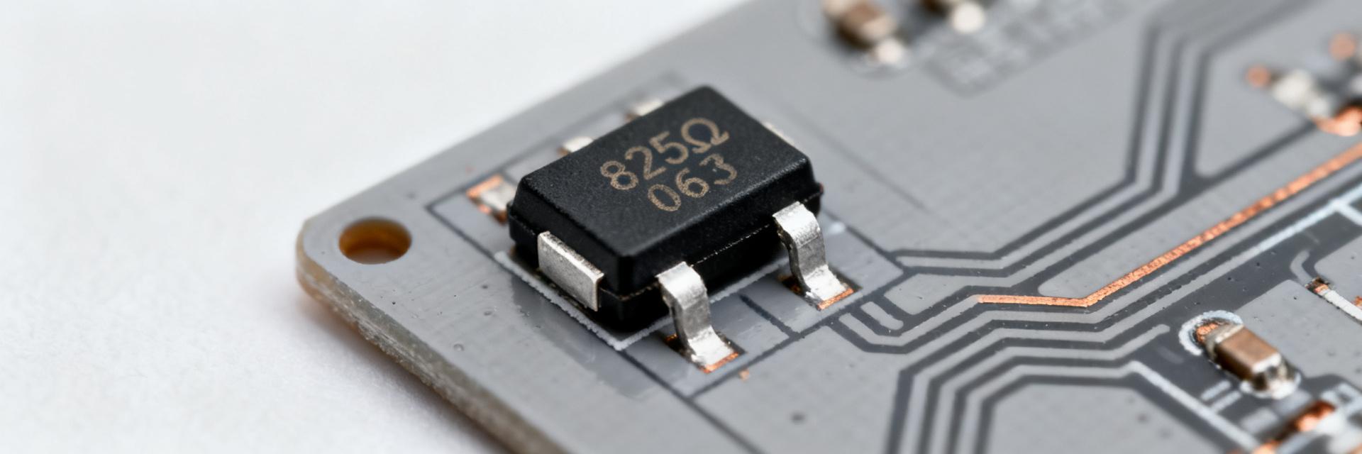
— At-a-glance electrical and physical specs
Point: Key nominal values summarize suitability for space-constrained designs. Evidence: Typical values used by engineers include nominal resistance 825 Ω, tolerance ±1%, rated power 0.1 W (1/10 W), package 0603 (1608 metric), common TCR ±100 ppm/°C, and operating range around −55°C to +155°C. Explanation: These specs define accuracy, thermal margin, and PCB placement constraints for signal and bias networks.
| Parameter | Typical Value |
|---|---|
| Nominal resistance | 825 Ω |
| Tolerance | ±1% |
| Power rating | 0.1 W |
| Package | 0603 (1608 metric) |
| TCR (typ) | ±100 ppm/°C |
| Operating temp | ≈ −55°C to +155°C |
— Typical applications and role on a PCB
Point: The 0603 resistor footprint with 0.1 W rating is optimized for compact consumer and IoT designs. Evidence: Common uses include pull-ups, feedback networks, signal conditioning, and current sensing in low-power paths. Explanation: The small size reduces routing area and parasitics but requires attention to derating and assembly; designers choose this family when board area and modest power dissipation dominate selection criteria and when the listed specs meet system accuracy targets.
2 — Electrical performance and limits (Data analysis)
— Resistance behavior: tolerance, TCR, and stability over time
Point: Tolerance and TCR determine baseline accuracy and temperature-induced drift. Evidence: A ±1% resistance tolerance sets initial error bands; TCR (for example ±100 ppm/°C) implies that a 50°C change produces about 0.5% shift in resistance. Explanation: For precision circuits, engineers should validate with 4-wire DCR measurements, room-temperature drift checks, and accelerated load-life to quantify long-term stability against the datasheet claims.
— Power handling, derating curve, and thermal considerations
Point: Board-level power capability is less than the rated 0.1 W in many ambient conditions. Evidence: The published 0.1 W is often valid at low ambient with ideal copper thermal path; on a small 0603 footprint, PCBs reduce heat-sinking so derating to 50–75% at elevated board temps is common. Explanation: Estimate temperature rise from P×Rth_board; include margin for continuous dissipation and follow component reflow limits for maximum assembly thermal exposure.
3 — Reliability, environmental specs & compliance (Data analysis)
— Reliability metrics and lifetime expectations
Point: Load-life stability and environmental cycling reveal real-world drift and failure modes. Evidence: Key parameters to request are load-life change (% drift after 1000+ hours), humidity/temperature cycling results, and solderability reports. Explanation: Use IEC/JEDEC-style tests as acceptance gates; prioritize parts with published load-life <0.5% drift for critical nets and require lot traceability to correlate field failures to manufacturing batches.
— Environmental limits and regulatory/rohs considerations
Point: Confirm operating/storage ranges and compliance marks before procurement. Evidence: Typical chip resistors list operating temps (≈ −55°C to +155°C), storage limits, and RoHS/REACH declarations; finishing affects solderability. Explanation: Verify the datasheet finish, confirm tin/lead-free plating compatibility with chosen assembly profile, and ensure that handling limits for moisture sensitivity are compatible with vendor packaging and incoming inspection.
4 — PCB footprint, assembly & inspection best practices (Method guide)
— Recommended PCB land pattern, placement, and pad finish
Point: A correct land pattern reduces tombstoning and cold joints. Evidence: For a 0603 part (approx. 1.6 × 0.8 mm body), recommended pad geometry often uses pads slightly longer than the termination length with controlled solder mask clearance and fillets. Explanation: Follow IPC-recommended patterns as a baseline; ensure adequate pad copper to provide thermal relief, avoid asymmetrical pad shapes, and keep large copper pours a safe distance to prevent uneven heating during reflow.
— Reflow profile, solder paste and inspection checklist
Point: Process control during reflow and paste selection determines assembly yield. Evidence: Typical profiles include controlled ramp, optional soak, and a peak near the paste manufacturer’s recommended peak (without exceeding component max). Explanation: Use a suitable no-clean SAC paste, follow recommended stencil apertures for 0603, and inspect post-reflow for good fillets, absence of tombstoning, and uniform wetting; include a visual checklist and sample X-ray or cross-section for failure analysis.
5 — How to choose RM06F8250CT vs equivalently rated parts (Method + Case)
— Matching critical specs and failure-mode tradeoffs
Point: Selection requires balancing electrical, thermal, and stability requirements. Evidence: If higher continuous power is needed, choose a larger package; if tighter temperature stability is required, select a precision resistor family with lower TCR. Explanation: Build a short decision flow: confirm resistance & tolerance, then verify TCR and load-life; if any item fails system needs, move to alternate families rather than overdriving the 0603 part.
— Sourcing, packaging options, and managing supply risk
Point: Packaging and lot control affect procurement and manufacturing continuity. Evidence: Common formats include cut tape and reel; minimum order quantities and lead times vary. Explanation: Stock alternates by spec set not only by part number, request certificate of conformity and lot test reports, and maintain a qualified second-source strategy to reduce single-vendor risk during high-volume production.
6 — Quick spec checklist and sample validation tests (Action recommendations)
— Pre-selection checklist for engineers and buyers
Point: A concise checklist reduces specification oversights. Evidence: Items: confirm nominal resistance & ±1% tolerance, verify power rating & derating, check TCR and load-life, confirm environmental ratings and RoHS, validate footprint and reflow profile, request sample and lot test data. Explanation: Use this checklist as a gate before ordering production volumes; require sample validation results matching each checklist item.
— Field validation tests to request or run
Point: Practical sample tests reveal batch-level issues before deployment. Evidence: Recommended tests include 4-wire DC resistance at multiple temps, bake & humidity soak, load-life at rated and overdrive power, solderability, and visual solder joint inspection. Explanation: Define pass thresholds (for example ≤0.5% drift after load-life for critical nets) and require vendor-supplied test data or run tests in-house on qualification lots.
Summary
- RM06F8250CT is a compact 0603 resistor with nominal 825 Ω and ±1% tolerance; its specs suit space-limited consumer and IoT PCBs but require thermal derating and assembly controls to meet reliability goals.
- Designers should validate TCR and load-life using 4-wire DCR and accelerated aging; power handling at the board level typically needs derating to ensure continuous operation within specs.
- Follow IPC land-pattern guidance, controlled reflow profiles, and a solder-paste/stencil strategy to avoid tombstoning and cold joints; request lot traceability and sample test reports before volume buys.
Frequently Asked Questions
What basic specs should be confirmed for RM06F8250CT before procurement?
Confirm nominal resistance, ±1% tolerance, stated power rating and recommended derating, published TCR, operating temperature range, and compliance declarations. Also request load-life and solderability data per lot to ensure vendor test results align with project acceptance criteria.
How should engineers validate RM06F8250CT on the bench and in thermal stress?
Run 4-wire DC resistance at ambient and elevated temps, perform humidity soak and bake tests, then execute load-life at rated and mild overdrive power. Use pass/fail thresholds tied to drift limits (for example ≤0.5% after load-life) to accept or reject batches.
Is the 0.1 W rating for RM06F8250CT usable for continuous dissipation on a small PCB?
Not always; the 0.1 W is a component rating under defined conditions. Board-level derating is common—designers frequently limit continuous dissipation to a conservative fraction (50–75%) depending on copper area and ambient. Estimate temperature rise from P×Rth_board and apply margin for continuous operation.
How does the TCR of RM06F8250CT affect precision analog circuitry over temperature?
With a TCR rating of ±100 ppm/°C, a temperature swing of 50°C yields an approximate 0.5% resistance drift. In precision applications like analog instrumentation amplifier feedback loops, this change can limit resolution. Engineers must evaluate this drift against system error margins.